

In today's manufacturing landscape, the variety of presses and measuring systems available for roll forming is more extensive than ever before. There are three major types of presses that roll forming professionals should know about: mechanical, air, and hydraulic presses.
By understanding the differences between them, you can make more informed equipment decisions that enhance your roll forming system's operations and design. Each type of press has unique advantages and disadvantages, and selecting the right one requires careful consideration of your application's specific needs and constraints.
In this series on our blog, we'll go through each press type one by one and discuss their features, advantages, and disadvantages and how all those elements make them the right choice for certain applications.
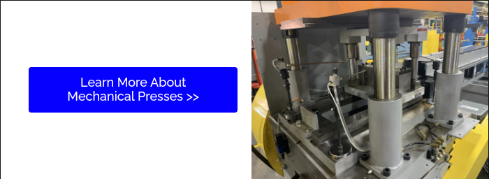
Mechanical Presses - Part 2
Mechanical Press Key Components
- Flywheel
- Function: The flywheel is a large, heavy wheel that stores kinetic energy. It is connected to an electric motor that keeps it spinning at a constant speed.
- Operation: The flywheel's energy is harnessed and transferred to other components to drive the pressing action.
- Crankshaft
- Function: The crankshaft is a shaft with one or more crank pins, typically designed in an offset manner, which translates rotational motion into reciprocating motion.
- Operation: As the flywheel rotates, it turns the crankshaft, causing it to move in a circular motion.
- Connecting Rods
- Function: These rods connect the crankshaft to the ram or slide.
- Operation: The connecting rods transfer the rotational motion of the crankshaft into the linear motion needed to move the ram up and down.
- Ram Movement (or Slide)
- Function: The ram is the part of the press that moves up and down, applying force to the material placed in the die.
- Operation: It carries the upper part of the die and moves in a straight line, driven by the connecting rods and crankshaft.
- Clutch and Brake System
- Function: The clutch engages the flywheel with the crankshaft to initiate the ram's movement, while the brake system stops the ram when necessary.
- Operation: The clutch connects and disconnects the flywheel’s rotational motion to the crankshaft, while the brake stops the flywheel and ram precisely.
Mechanical Press Operation Processes
- Power-Up: The electric motor powers up and spins the flywheel, storing kinetic energy.
- Engagement: The operator or an automated control system engages the clutch, connecting the spinning flywheel to the crankshaft. This starts the transfer of energy.
- Crankshaft Rotation: As the flywheel turns the crankshaft, the crankshaft’s offset pins push and pull the connecting rods, converting the rotational motion into linear motion.
- Ram Movement: The connecting rods drive the ram downward towards the material placed in the die. The force applied by the ram is used to shape, cut, or press the material as needed.
- Pressing Action: As the ram reaches the bottom of its stroke, maximum force is applied to the material. Depending on the design, the press may perform a single stroke or continuous strokes.
- Return Stroke: After the pressing action, the ram is pulled back up by the continuous rotation of the crankshaft, completing the cycle. The brake can stop the ram at the desired position.
- Repeat: The process repeats for each cycle, with the flywheel maintaining a constant speed to ensure consistent force and timing.
Mechanical presses are valued in roll forming for their high-speed operation, precision, and durability. The high-speed, consistent stroke these presses offer makes them the ideal choice for high-volume production where accuracy and timing are critical. When synchronized with the roll forming line, the mechanical press cycles at high speeds to deliver precise, repeatable force at a specific point in the production process.