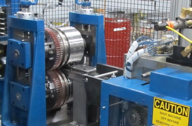
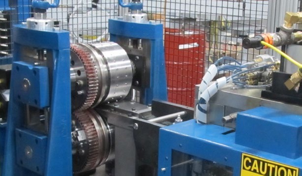
Rotary punching uses a set of mating rolls. The top roll has punches and the bottom roll has die openings. The material is punched, lanced, or formed as it is pulled through the rotating rolls and the punches in the top roll meet their mating roll die openings using alignment rolls and wire EDM antibacklash gears.
How Rotary Punching Works in Roll Forming
The length of the pattern or patterns to be punched, as well as the line speed that needs to be achieved, determines the diameter of the rolls. The roll diameter is not as critical for servo-driven units as for nonservo units.

Fixed or Cam Style
Two distinct styles of rotary units are fixed and cam. With a fixed punch or shear, the punches do not move inside the fixed upper roll. This style normally is used when the part features, such as holes, are continuous down the length of the part.
In a cam-in rotary unit, a solid or mechanical cam activates the punches so they actually move up and down inside a punch roll, similar to the movement of a punching machine. This means that structural components with material thicknesses up to 12-gauge, such as building joists, can be punched with rotary units.
A cam-in and some fixed-style units can be programmed to punch in specific locations, thereby allowing the punching of irregular patterns that are not continuous down the length of the part.
Both styles have similar construction. The rolls are made of either prehardened steel or are tool steel-hardened.
The type of roll material used depends on many factors, the most important of which are the speed that the unit must run; the gauge of the material to be punched, lanced, or formed; and the durability required (low, medium, or high production).


